Hydricity Blog

Fabrication of Alpha Prototype
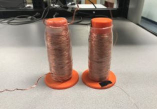
After creating the optimized design for the induction system, the team purchased the necessary materials to construct a prototype. The first component to be produced was the coil mount. This part consists of a hollow cylindrical tube with a small flange on the bottom, the ladder of which will eventually be used as a mounting surface (See Fig. 2). This part creates a structure for the coil to wrap around and a channel for the magnet to travel through, while keeping a waterproof barrier so that the magnet can induce a current in the coil without exposing any electronic components to moisture. For the alpha prototype, the coil mount was 3D printed using PLA plastic, which is highly hydrophobic. After the mount was made, the coil winding process began. After extensive research, there was still uncertainty whether or not the 9 overlapping coils should be wired in series or parallel, so the team decided to construct one iteration of each and compare both wiring methods through testing (See Fig. 3).
Figure 2: Coil Mount
The coil wired in parallel consisted of 9 separate segments of wire that were individually wrapped around the mount starting at the base. After the first segment of wire was coiled over the entire mount, a new segment was started to overlap this and so on. After all 9 layers were completed, the enamel was removed from the ends of the wires and each wire was then twisted together. The coil wired in series consisted of a single strand of wire. This wire was wrapped around the mount starting at the base and until reaching the top. At this point, the wire was wrapped back down the support in the opposite direction to create a continuous single coil. After this layering process had been carried out 9 times, the induction system wired in series was completed. To finalize the construction process, waterproof heat-shrink tubing was used to cover each induction system, which would secure the coils as well as protect the prototypes from the elements. Finally, the team decided it would be best to test a third style of coil. This third coil is set to be complete in the coming days, as a third coil mount had to be created before testing could begin. The pattern for wrapping the third coil will also be in series. It will be a continuous run of copper wiring, similar to the second coil created. This time however, once a full wrap is completed, the end of the wire will be pulled vertically back to the base of the coil mount so that the wrapping process can start again. The team is theorizing that having all of the coils wrapped in the same direction will cause a slight increase in the power generated since the magnetic field of the copper will be more uniform.
Figure 3: Parallel and Series Induction System Prototypes